
Intraoperative cone beam computed tomography in craniomaxillofacial traumatology – a case report
Authors:
Š. Pohanka 1,2; J. Šimek 1,2; V. Dolina 1,3; M. Hozová 1; P. Novotný 1
Authors‘ workplace:
Department of Oral and Maxillofacial Surgery, Tomáš Baťa Hospital, Zlín, Czch Republic
1; Department of Oral and Maxillofacial Surgery, Faculty of Medicine, Masaryk University, Brno, Czech Republic
2; Department of Oral and Maxillofacial Surgery, University Hospital Olomouc and Faculty of Medicine and Dentistry, Palacký University, Olomouc, Czech Republic
3
Published in:
ACTA CHIRURGIAE PLASTICAE, 67, 4, 2025, pp. 252-259
doi:
https://doi.org/10.48095/ccachp2025252
Introduction – history and technology
The development of medical x-ray computed tomography (CT) is generally credited to two physicists: Drs. G. N. Hounsfield and A. M. Cormack. In 1963, Cormack reported findings from investigations of perhaps the first CT scanner actually built (Cormack 1963). The first clinically available CT device was installed at Atkinson Morley Hospital (London, England) in September 1971 [1].
In 1998 and 1999, Arai et al. in Japan and Mozzo et al. in Italy, working independently, introduced cone beam computed tomography (CBCT) for oral and maxillofacial applications and, like CT, offered 3D exploration and more accurate imaging compared to 2D imaging [2].
Conventional computed tomography equipment using a fan-shaped X-ray beam captures a series of axial plane slices or from a continuous spiral motion over the axial plane [2].
CBCT imaging is performed using a rotating platform to which an X-ray source and detector are fixed. A cone-shaped source of ionising radiation is directed through the middle of the region of interest (ROI) and the transmitted, attenuated radiation is projected onto an area X-ray detector on the opposite side. The X-ray source and detector rotate around a fulcrum, fixed within the centre of the ROI (Fig. 1). Unlike multislice spiral computed tomography (MSCT), the subject to be imaged does not move. This fulcrum acts as the center of the final acquired volume imaged. During the rotation, multiple sequential planar projection images covered by the detector or field of view (FOV) are acquired in an arc 180° or greater. These single projection transmission images constitute a basis, frame, or raw images. Basis images seem similar to cephalometric radiographic images, only each is slightly offset from the next. There are usually several hundred projection-basis images that are integrated by software to construct an image volume. Only one rotational sequence of the gantry is necessary for CBCT to acquire enough data for volumetric image construction because the FOV is irradiated simultaneously [3].

There are different types of CBCT gantries relative to patient position during image acquisition: seated patient position, standing patient position, supine patient position. Regarding the arc of rotation, for some scanners, a partial rotation is used out of necessity, as a full rotation is not possible owing to mechanical obstruction of the C-arm. Other devices allow for the selection of a half or full rotation. In terms of image quality, a partial rotation tends to decrease overall image quality; this is mainly apparent in the amount of noise [4].
CBCT has become very popular not only in dentistry and oral and maxillofacial surgery but also in other surgical fields, such as in ENT for verification of cochlear implant placement [5]. In neurosurgery for the spinal navigation or skull-base surgery [6,7], in orthopaedics for limb injuries [8] or in plastic surgery, e. g., for planning rhinoplasties [9]. Its spectrum of use still rises.
Hybrid operating rooms combine medical imaging and conventional surgical suites into one treatment space and can be used for both minimally invasive and open surgical procedures. They allow surgeons to perform imaging, biopsy, diagnosis, and surgery all in the same room and remove the need to move a patient between an imaging suite and an operating room [10]. According to this definition, we could say that intraoperative CBCT applications can also be counted.
Case descriptions
T. Bata Regional Hospital in Zlin has possessed intraperative robotic O-gantry CBCT since June 2021. It is located in a neurosurgical station of central operating rooms, mostly used for navigation in spinal surgery. For maxillofacial cases, it is available on demand and operated by a certified radiographic technician. With its maximal FOV 25 × 25 × 60 cm, it is suitable for maxillofacial area imaging, and our surgeons can use it for selected cases (Fig. 2).

The authors would like to present five cases, one secondary and four primary reconstructions for craniomaxillofacial trauma, where the intraoperative CBCT was used.
Case 1
The first case is a young man who suffered a polytrauma injury after a fall from the 14th floor. Primary treatment in other trauma center was targeted mainly on stabilisation according to damage control surgery protocol, as the prognosis of life was uncertain. Concerning facial bones, he suffered panfacial trauma: displaced comminuted bilateral Le Fort I + II + III fracture, sagittal fracture of the hard palate, left orbital floor fracture, and mandibular body fracture.
First stage repair of the craniomaxillofacial area the 7th day after injury consisted of load-sharing open reduction and internal fixation (ORIF) of the mandible, reconstruction of the left orbital base with titanium mash, high Adam’s ligatures for midfacial stabilisation, intermaxillary fixation with arch bars, fixation of frontozygomatic sutures with osteosynthetic plates and screws, and a tracheotomy. After the primary surgical treatment, he was referred to the intensive care unit of his hometown. After general stabilisation, he was referred to our department for reevaluation and further treatment one month after the injury.
The findings were blindness of the right eye due to optic nerve trauma, enophthalmos of the left eye, traumatic telecantus, lagopthalmos of the left eye due to the lower lid retraction caused by previous infraorbital incision approach, bland dish face with anterior open crossbite, and loose wires of intermaxillary fixation. Intraoraly healed surgical incisions, missing teeth: left upper central and lateral incisors and right lower lateral incisor, scarred sagittal tear of soft palate – traumatic cleft with open hypernasality.
The decision for reoperation was made after discussion with the patient. The plan was to do a staged surgery. In the first stage to re-estabilish all three facial dimensions and proper occlusion by releasing fracture lines, reduction of fragments, narrowing of the interorbital distance, and re-ORIF of fractures. Left orbital floor reconstruction was left untouched due to vision present only on the left eye and subsequent potential risks of blindness. Since there were fracture lines in both dental arches, the concern of the arch widening and condylar displacement was discussed. We decided to use intraoperative CBCT imaging for the optimal result. During the operation, two series were obtained. The first showed good condylar-fossa relationship with use of interdental wire ligated between lower first molars over the tongue and also adequate interorbital relation. Apart from that, there was an asymmetry in zygoma bone projection, which was then corrected with a better alignment on the sphenozygomatic suture (Fig. 3, 4).


The second operation concerned the removal of dental arch bars, rigid endoscopy for soft palate evaluation, and release of the left lower lid scar with a full-thicknes skin graft from the ipsilateral upper eyelid. The third stage was correction of the post-tracheostomy scar, Furlow Z-plasty for the traumatic soft palate cleft, fat augmentation under the lower lid skin graft, and alveolar bone augmentation before teeth reconstruction with dental implants. Currently, the patient is in the process of dental rehabilitation and speech therapy after the soft palate surgery.
Case 2
Here we present a case of a 45-year-old patient who fell from a bicycle and spent the night injured in the scarp next to the road. After admission into the trauma centre he had Glasgow Coma Scale 15, was hypothermic, and suffered panfacial and craniocerebral trauma: comminuted frontal bone fracture including both orbital roofs, frontobasal brain contusion and dislocated bony fragment, bilateral Le Fort III fracture, right zygomaticomaxillary complex fracture, naso-orbito-ethmoidal fracture, sagittal maxillary fracture between upper right central and lateral incisor, comminuted fracture of the mandibular body with bone loss, simultaneous fractures of transversal processes of C6 and C7, OA A2 Th7 body fracture, and fracture of the right 1st rib and contusion of the right lower pulmonary lobe.
The patient was operated on the day of admission as a collaborative neurosurgical-maxillofacial reconstruction. From the maxillofacial aspect, a tracheotomy was performed, followed by the ORIF of the upper and middle facial third in a top-down manner. With the use of dental arch bars and temporary mandible osteosynthesis, the intermaxillary fixation was performed. At this point, the intraoperative CBCT was done, and actual bone reduction was evaluated. Except for the nasal root, all the fragments were in satisfactory position. Re-ORIF of the nasal root bone was performed. Afterwards, cranialization of the frontal sinus and duroplasty with pericranial flap by a neurosurgeon followed. Spine operative stabilisation was performed several days later.
Case 3
This was the case of a 71-year-old cyclist who flew over the handlebars without a helmet in the state of alcohol intoxication. He suffered a comminuted displaced bilateral Le Fort I + II fracture, comminutive fracture of the mandibular alveolus with loss of the lower incisors and right lower canine, a nasal bone fracture, and a penetrating wound of the lower lip.
After primary treatment of the soft tissue wound and mandibular alveolar fracture on the day of the injury, definitive treatment of the facial skeleton was done the next day. Intraoperative CBCT before wound closure showed a still-displaced fragment of the right nasal bone and frontal maxillary process, though the clinical appearance of the nose seemed appropriate. The nasal septum was also mildly deviated by the nasal packing pressure. According to these findings, the position of the fragments was rearranged immediately (Fig. 5).

Case 4
The fourth case was a 42-year-old lady who was kicked in the face by a horse during a fall from it.
Luckily she suffered only minimally displaced Le Fort I and nasal bones fracture with contusion of the facial soft tissues. Given the fact that the maloclussion was present, she was operated on the day of the trauma. After mobilisation of the maxila with the Rowe-Kelly forceps, intermaxillary fixation with screws and wires was made, followed by load-sharing plate osteosynthesis. Although there was a little concern about the proper nasal bones alignment based on subtle overall facial asymetry, the intraoperative CBCT showed satisfactory position of the nasal bones (Fig. 6).


Case 5
The fifth case was a 61-year-old lady who felt in sleep from a bunk bed onto a bedside table. She suffered from a displaced fracture of the medial wall and base of the left orbit, minimally displaced nasal bone fracture, facial abrasions and closed displaced fracture of the left distal radius. The forearm fracture was treated conservatively by a traumatologist. The patient had painful restriction in a down gaze on the left eye, and according to the severity of the displacement, she was operated on after swelling decreased on the 6th day after trauma. First, a mirrored 3D model of the unaffected orbit was printed, anatomical preformed titanium mash was prebend, thereafter with the use of exoscope magnification a transconjunctival-transcaruncullar preseptal approach was made and the orbital walls were reconstructed. A closed reduction of the nasal bones was done. Perioperative CBCT showed an inaccurate position of the posterior margin of the reconstructive implant, and therefore the position was corrected. The second CBCT confirmed its appropriate position (Fig. 8).
Discussion
The authors infrequently doubt the necessity of postoperative X-ray imaging in traumatology. Nevertheless, Van den Bergh et al. did not find routine postoperative radiography necessary after surgical treatment of maxillofacial trauma, suggesting that avoiding routine postoperative radiography will lead to a reduction in exposure of patients to ionising radiation, a reduction of costs, and probably a more efficient discharge [11].
Otherwise, there are some certain situations when the postoperative imaging could be highly beneficial.
Even in the case of ORIF, the anatomy of facial bones and patterns of the fracture often prevent direct visualisation of all fracture lines. Also, it is not appropriate to deperiost large areas and smaller fragments of bone; thus, it could compromise a blood supply and healing. Commonly present swelling can also mask the asymetrical position of fractured bones. In these situations, the postoperative image can show previously hidden undesirable results and can lead to the decision for reoperation. In a case of „closed reduction,“ the postoperative appearance of fragments on an X-ray could certify a successful alignment as well.
If not available intraoperatively, standard practice is to obtain postoperative images the day after operation.
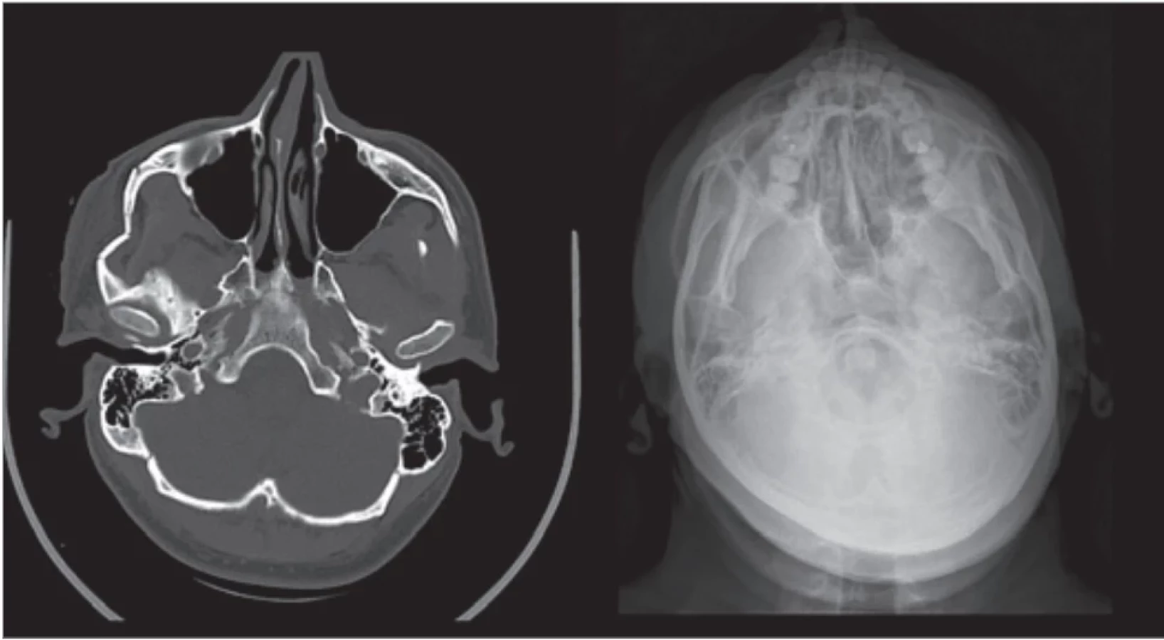
Ordinarily, it used to be 2D X-ray pictures. In simple cases, usually plain radiographs – with effort for perpendicular relationship between images. For mandibular fractures, an ortopantomogram (OPG) and posterio-anterior (PA) radiograph of the face with an open jaw (Clementschitsch radiograph). For midfacial and upper facial fractures, PA radiograph of the skull, lateral X-ray of the skull, and radiograph in Watters projection. For zygoma arch and zygoma bone, also axial skull radiograph (Fig. 8).
Use of plain radiographs may not be sufficient in certain anatomical locations. This may apply, for example, in the orbital region on account of the superimposition of bony structures.
Postoperative 3D imaging with MSCT was reserved for complicated cases and specific conditions like severe comminution, concurrent intracranial injury with pneumocephalus, or intracranial bleeding.
The AO CMF Surgery reference suggests particularly that a panfacial fracture should have good postoperative radiologic documentation of a proper reduction [13].
Nowadays many maxillofacial departments have available CBCT for diagnosing a broad spectrum of facial bone conditions and successfully use it also in traumatology, but not everywhere on the theatre.
Current CBCT machines designed for use in the operating room mildly constitute an opportunity for immediate intraoperative imaging and the possibility for prompt adjustment of fragments and osteosynthetic material position.
The authors who used intraoperative CBCT verification before wound closure didn’t report the need for a secondary surgical procedure. The main advantages reported by teams using intraoperative CBCT were immediate and rapid evaluation of the adequacy of bone repositioning, avoidance of further surgical revisions, which entail additional costs and increased morbidity, ease of handling, elimination of the need for radiographic technicians, radiation dose reduction of 50% compared with MSCT, elimination of radiographic verification after surgery, lower level of metal artefacts, quality comparable to MSCT for the facial skeleton, average examination time faster than intraoperative MSCT (10 vs. 30 min), and lower costs than with mobile MSCT [14].
Personally, we found the intraoperative CBCT useful in all presented cases. In four out of five cases, certain adjustments of fragments were made after the first image was obtained, and in the last case, the correct source of asymetry was detected.
Routinely, the postoperative image is made the day after the operation at our department. There are always a few cases per year that we indicate for the reoperation. As the literature suggests, routine intraoperative CBCT imaging could decrease these numbers with a negligible increase in the X-ray exposure risk. Values for the head imaging in our devices are summarized in Tab. 1. On the other hand, it has to be mentioned the costliness of the intraoperative CBCT machine and the need for the other suitable equipment of the OR, such as appropriate X-ray-transparent tables, X-ray protection, etc (Fig. 9).


Conclusion
Intraoperative CBCT imaging can be beneficial, especially in panfacial fractures to check if the estabilishment of all three dimensions of the facial skeleton was successful; in comminuted fractures, for localising the position of all small fragments, where some of them can interfere with anatomy or function (orbital walls, skull base, ostia of paranasal sinuses, optic canal etc.). In fractures of the nasoorbitoethmoidal complex, with the necessity of medial canthi reconstruction as a prevention of postoperative traumatic telecanthus. In fractures, violating dental arches to prevent widening of the maxila or mandible and estabilishing a proper condylar position. In orbital reconstruction to prevent unhappy placement of titanium mashes. In zygoma fractures to form appropriate symetry. In condylar fractures for anatomical reduction.
As the intraoperative CBCT examination prevents need for revision surgery and lowers radiation dose with good quality bone image, authors express hope for more frequent use of this method in the future as it becomes more affordable and widespread among maxillofacial surgery units as it also can be used in other subspecialties than trauma surgery. As technology evolves, we hope to integrate with other modalities such as augmented reality, intraoperative navigation, and more to ensure meticulous patient care.
Roles of authors
MDDr. et MUDr. Štěpán Pohanka, FEBOMFS – manuscript writting, literature research, treatment of the patient; MUDr. et MUDr. Jiří Šimek, Ph.D, FEBOMFS – treatment of the patient, supervision; MDDr. Pavel Novotný – treatment of the patient; MDDr. Monika Hozová – treatment of the patient; MDDr. Vít Dolina – treatment of the patient, literature research.
Disclosure
The authors have no conflict of interest to disclose. The authors declare that this study has received no financial support. All procedures preformed in this study involving human participants were in accordance with ethical standards of the institutional and/or national research committee and with the Helsinki declaration and its later amnedments of comparable ethical standard.
Sources
1. Shaw CC. Cone beam computed tomography. Gestational diabetes. Boca Raton: CRC Press 2014.
2. Venkatesh E., Elluru SV. Cone beam computed tomography: basics and applications in dentistry. J Istanb Univ Fac Dent. 2017, 51 (Suppl 1): S102–S121.
3. Jaju PP. Cone beam computed tomography. New Delhi: Jaypee Brothers Medical Publishers 2015.
4. Pauwels R., Araki K., Siewerdsen JH., et al. Technical aspects of dental CBCT: state of the art. Dentomaxillofac Radiol. 2015, 44 (1): 20140224.
5. Ruivo J., Mermuys K., Bacher K., et al. Cone beam computed tomography, a low-dose imaging technique in the postoperative assessment of cochlear implantation. Otol Neurotol. 2009, 30 (3): 299–303.
6. Nottmeier EW., Bowman C., Nelson KL. Surgeon radiation exposure in cone beam computed tomography-based, image-guided spinal surgery. Int J Med Robot. 2012, 8 (2): 196–200.
7. Lee S., Gallia GL., Reh DD., et al. Intraoperative C-arm cone-beam computed tomography: quantitative analysis of surgical performance in skull base surgery. Laryngoscope. 2012, 122 (9): 1925–1932.
8. Bailey J., Solan M., Moore E. Cone-beam computed tomography in orthopaedics. Orthopaed Trauma. 2022, 36 (4): 194–201.
9. Robotti E., Daniel RK., Leone F. Cone-beam computed tomography: a user-friendly, practical roadmap to the planning and execution of every rhinoplasty – a 5-year review. Plast Reconstr Surg. 2021, 147 (5): 749e–762e.
10. Clark M., Horton J. Hybrid operating room suites: CADTH horizon scan. 2023 [online]. Available from: https: //www.ncbi.nlm.nih.gov/books/NBK595334/.
11. van den Bergh B., Goey Y., Forouzanfar T. Postoperative radiographs after maxillofacial trauma: sense or nonsense? Int J Oral Maxillofac Surg. 2011, 40 (12): 1373–1376.
12. Fonseca RJ., Marciani RD., Turvey TA. Oral and maxillofacial surgery. St. Louis: Saunders/Elsevier 2009.
13. Cornelius CP., Gellrich N., Hillerup S. Panfacial fractures (sequencing of repair). [online]. Available from: https: //surgeryreference.aofoundation.org/cmf/trauma/midface/further-reading/panfacial-fractures-sequencing-of - repair.
14. Assouline SL., Meyer C., Weber E., et al. How useful is intraoperative cone beam computed tomography in maxillofacial surgery? An overview of the current literature. Int J Oral Maxillofac Surg. 2021, 50 (2): 198–204.
MDDr. et MUDr. Štěpán Pohanka, FEBOMFS
Krajská nemocnice T. Bati, a. s.
Havlíčkovo nábřeží 600,
762 75 Zlín
stepan.pohanka@bnzlin.cz
Submitted: 29. 3. 2025
Accepted: 6. 12. 2025
Labels
Plastic surgery Orthopaedics Burns medicine TraumatologyArticle was published in
Acta chirurgiae plasticae

2025 Issue 4
Most read in this issue
- Treatment and outcomes of rectus diastasis in post-bariatric patients and postpartum women – a systematic review
- Anterior approach to posterior auricular artery in microvascular anastomosis – a new concept in replanting amputated ears – experience from four successful cases and literature review
- Association between the maxillofacial injury severity score to helmet types, neutrophil lymphocyte ratio and length of stay
- Post-otoplasty keloid scars – treatment strategies and case reports