-
Medical journals
- Career
EXPERIMENTAL ANALYSIS OF THE LUMBAR SPINE KINEMATICS
Authors: Lubos Tomsovsky 1; Petr Kubovy 2; Martin Otahal 1
Authors‘ workplace: Czech Technical University in Prague, Faculty of Biomedical Engineering, Kladno, Czech Republic 1; Charles University in Prague, Faculty of Physical Education and Sport, Prague, Czech Republic 2
Published in: Lékař a technika - Clinician and Technology No. 2, 2017, 47, 49-55
Category: Original research
Overview
Pain-provoking disorders of the lumbar spine affect most of adult population and nearly everyone suffers from some of them during their lifetime. A common symptom of diseases, injuries or inevitable changes in the area of lumbar spine is known as the Low Back Pain (LBP). A chronic form of the LBP, called the Low Back Pain syndrome, is mostly caused by degenerative changes of intervertebral discs of the lowest intervertebral joints. The work was focused on in vitro analysis of the porcine lumbar spine kinematics. Two last neighbouring intervertebral joints without active tissue, L4/5 and L5/6, were used. The total number of fifteen cadaveric samples of porcine lumbar spine was involved. A unique loading mechanism was designed and constructed for the purposes of this study. Samples were loaded by flexion/extension movement within the physiological range of motion of ± 5°, in a quasistatic mode. The recording and analysing of the lumbar spine kinematics was realized by the motion capture camera system (Qualisys AB, Göteborg, Sweden). The results showed that the so-called instantaneous axis of rotation (IAR), or the corresponding instantaneous centre of rotation (ICR), was an adequate objective parameter for the assessment of the lumbar spine kinematics. Its position was comparable across all samples and situated very close to the spinal canal. For the purposes of this work, an altered artificial disc of a ball-and-socket type (ProSpon, Ltd., Kladno, Czech Republic) was used to study the kinematics of two neighbouring joints after the disc replacement in the area of a caudally situated one. The results of this comparative analysis showed a significant influence of the artificial disc on the kinematics of both, caudally situated joint, where the disc was implanted, and the adjacent one.
Keywords:
low back pain, kinematics, intervertebral joint, instantaneous centre of rotation (ICR), artificial discIntroduction
The lumbar spine, as well as the whole spine, is a very complicated and complex system that consists of active structures, passive structures and nerves [1]. As the section that bears and supports the upper-body weight, the lumbar spine is very vulnerable to many pain-provoking disorders. More than 60% of all adults are affected by some of lumbar spine diseases during their lifetime with a common symptom called Low Back Pain (LBP) [2, 3].
When the duration of the pain is greater than 12 weeks a chronic form of the LBP, called a LBP syndrome, appears [4]. It affects up to 20% of adult population [5]. It is mostly caused by degenerative changes of intervertebral discs of last two intervertebral joints [2, 6] with a prevalence ranging between 30
and 50% [7]. The LBP syndrome might then result
in an intervertebral disc replacement. Unfortunately contemporary artificial discs often fail due to their design, construction or technique of the implantation [8, 9].Studying the behaviour of the lumbar spine during a movement is one of the methods how to assess its proper functioning [10]. The kinematical analysis is a useful tool for this purpose as the condition and mechanical properties of all individual spinal structures are outright reflected in it [11]. The so-called instantaneous axis of rotation (IAR), or the corresponding instantaneous centre of rotation (ICR) in plane, is shown to be an adequate, objective parameter for the analysis and assessment of the spinal kinematics among samples [12, 13, 14].
Before the experiment itself, we defined three hypotheses to research in this study:
- The position of the ICR is similar across all samples loaded by the same loading cycle.
- The ICR is situated close to the spinal canal.
- The artificial intervertebral disc, implanted in the L5/6 area, changes the kinematics in L5/6 and also in the neighbouring FSU (L4/8).
Theoretical background
There are three most important terms that relate to this issue. The first one is a functional spinal unit (FSU) that is represented by one intervertebral joint without active structures [10, 15].
The FSU consists of two neighbouring vertebrae, intervertebral disc between them and adjacent ligaments [13]. Sometimes it is also described as a system of three joints, two zygapophyseal joints in the back (in the dorsal direction) and the third one represented by intervertebral disc between vertebral bodies [16].
Fig. 1: Two functional spinal units with the description of passive structures. 
The second term is the so-called coupled movement. It’s a movement of each intervertebral joint that, together with contributions from other joints of the spine, results in macroscopic movement of the spine as a whole [6, 17, 18]. As the most significant movement of the lumbar spine [6, 19], flexion/extension consists of sagittal rotation and sagittal translation, as shown in Fig. 2 [6, 17, 18, 20].
Fig. 2: Flexion/extension as a coupled movement of the lumbar spine. 
The third term is the instantaneous axis of rotation (IAR), or the corresponding ICR in plane. It’s a phenomenon that represents an axis or a point, around which the body rotates in the space or in the plane [14]. It’s a place of zero net force during the movement, which also means the place without any kind of deformation [6, 10]. Its position is a function of each contributions of the coupled movement at a given time [12, 13]. The description of a coupled movement using the IAR (ICR) is shown in Fig. 3.
Fig. 3: A schematic representation of the description of the coupled movement using the IAR (ICR) (R<sub>0</sub> is a position vector determining the position of the origin of IAR; L represents a translation along the axis and the angle φ represents a rotation about the axis) [10]. ![Fig. 3: A schematic representation of the description of the coupled movement using the IAR (ICR) (R<sub>0</sub> is a position vector determining the position of the origin of IAR; L represents a translation along the axis and the angle φ represents a rotation about the axis) [10].](https://pl-master.mdcdn.cz/media/image/d7dbebddfbe2ed96c2027f5af1369728.jpg?version=1537797141)
Materials and methods
Samples and their preparation
The study was focused on in vitro measurements of the lumbar spine kinematics due to feasibility of the experiment, availability of samples and from ethical point of view. For the purposes of experimental analysis cadaveric porcine lumbar spine samples were used. It is proven that the porcine lumbar spine is a representative model of the human lumbar spine as regards the anatomical and biomechanical similarities [21, 22]. However, the porcine spine has six lumbar vertebrae compared to five vertebrae of the human spine. The last two vertebrae of the human spine are the most vulnerable structures to many pain-provoking disorders, which is why the segment L4–L6 of the porcine spine was used to study two neighbouring FSUs.
Fig. 4: The preparation of the samples. 
The samples were gained from individuals of 3/4–2 years old right after being butchered, which ensured their freshness. The samples were then transported to the laboratory in a fast way to eliminate their possible degradation. Finally the L4–L6 segment was extracted from the porcine spine and deprived of muscle tissue to study the kinematics of FSUs.
Polyurethane resin of Axson F16 (AXSON Technologies, Saint Ouen l'Aumône, France) was used to prepare castings of a cranial and caudal end of a sample, as shown in Fig. 4. These castings provided mounting of samples to a loading mechanism. The total number of fifteen cadaveric samples of porcine spine was involved in this work.
The loading mechanism
The loading of the samples was realized through the unique loading mechanism that was designed for this purpose. The device enables to load the samples by all lumbar movements in their physiological, even non-physiological ranges of motion. It also allows analysing combinations of movements. Due to its unique construction, the system provides static, quasistatic and also dynamic experimental measurements of the lumbar spine.
Fig. 5: The unique loading mechanism. 
The construction and control of the device also ensures the loading of samples by pure bending about a fixed point. Such loading corresponds to movements of the whole spine on a macroscopic level. The fixed point was situated at the very caudal end of a sample and the radius of curvature was equal to the length of a sample.
The recording apparatus
The commercial motion capture camera system was used for recording and analysing the lumbar spine kinematics. Four cameras were chosen as a sufficient number to capture the whole space of samples loading precisely. The accuracy of measurements is also influenced by the size, visibility and number of markers [23]. Special right-angle beams were made for fixing eight markers on each vertebra. This number seemed to be sufficient for high measurement accuracy, as the average residual value for each camera was always less than 0.5 mm when calibrated. This was a quality check of the marker’s measured position.
Fig. 6: The recording device on the left. The markers mounted to the sample on the right. 
The loading cycle
The experimental analysis was focused on the kinematical analysis of flexion/extension movement. For the purposes of this study, the quasistatic loading cycle applied to the cranial end of L4 was used. The loading was realized in the physiological range of motion of ± 5°.
The assessment of the kinematics was based on the comparison of the ICR positions between the samples without an artificial disc and samples with the artificial disc implanted in the area of L5/6. For the purposes of this study, the artificial disc was used. The disc is an altered ball-and-socket type device, as shown in Fig. 7. The implant was adjusted to the size of the porcine lumbar spine proportionally.
Fig. 7: The artificial disc of a ball-and-socket type on the left; the implantation of the disc in the area of L<sub>5</sub>/<sub>6</sub>. 
Results
The kinematical analysis of two neighbouring FSUs, L4/5 and L5/6, without the artificial disc
At first the position of the ICR in two FSUs, L4/5 and L5/6, was analysed. The Tab. 1 shows the mean positions of ICR for both joints during a complete loading cycle and also their mean position in maximal flexion and extension. The results are presented in the local coordinate system of caudally situated vertebra to study relative movements between two neighbouring vertebrae. Transversal motions were neglected, because their contributions to the coupled movement of flexion/extension were insignificant [5]. The data were processed in sagittal plane; X-values represent positions of the ICR along horizontal axis, Y-values represent positions of the ICR along vertical axis. The results are presented together with standard deviations (std) in brackets.
1. The mean values of positions of the ICR. 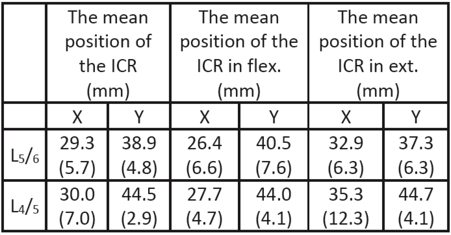
The results of this part of the experiment proved our hypotheses. The position of the ICR is comparable across all samples and this position is situated very close to the spinal canal based on knowledge of anatomical dimensions of the porcine lumbar spine, as shown in Fig. 8.
Fig. 8: The illustrative diagram of results based on anatomical dimensions of the porcine lumbar spine with standard deviations (std) in brackets; the diagram represents samples of three neighbouring vertebrae, each of them consisting of a vertebral body (VB) and a spinous process (SP). Two adjacent vertebrae are connected by an intervertebral disc (IVD) and by ligaments that are not depicted to make the diagram clear. Ellipses represent error bars of standard devia-tions, where the red represent the results for complete loading cycle, the blue represent the data for extension and the green for flexion, with mean presented as the black cross in the middle. 
The comparative kinematical analysis of two neigh-bouring FSUs, L4/5 and L5/6, with the artificial disc implanted in the L5/6 area
This part of experiment was focused on kinematical comparison of the behaviour of two FSUs, L4/5 and L5/6, after the implantation of an artificial disc in the L5/6 area. The Tab. 2 shows the mean positions of the ICR for both joints during a complete loading cycle and also their mean position in maximal flexion and extension.
2. The mean values of positions of the ICR after implantation of the artificial disc into L<sub>5</sub>/<sub>6</sub> area. 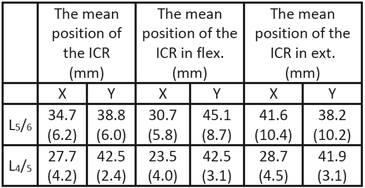
The results of this part showed that the kinematics was changed not only in the area of L5/6, where the artificial disc was implanted, but also in the area of neighbouring FSU, L4/5, as shown in Fig. 9.
Fig. 9: The illustrative diagram of results based on anatomical dimensions of the porcine lumbar spine; the diagram represents samples of three neighbouring vertebrae, each of them consisting of a vertebral body (VB) and a spinous process (SP). Two adjacent vertebrae are connected by an intervertebral disc (IVD) and by ligaments that are not depicted to make the diagram clear. Ellipses represent error bars of standard deviations, where the red represent the results for complete loading cycle, the blue represent the data for extension and the green for flexion, with mean presented as the black cross in the middle. 
Tab. 3 and Tab. 4 contain the results of statistical analysis that prove or disprove the influence of artificial disc on the kinematics of FSUs. Two sample T-test was used for statistical analysis.
3. The results of the statistical analysis for the FSU of L<sub>5</sub>/<sub>6</sub>, where the artificial disc was implanted. 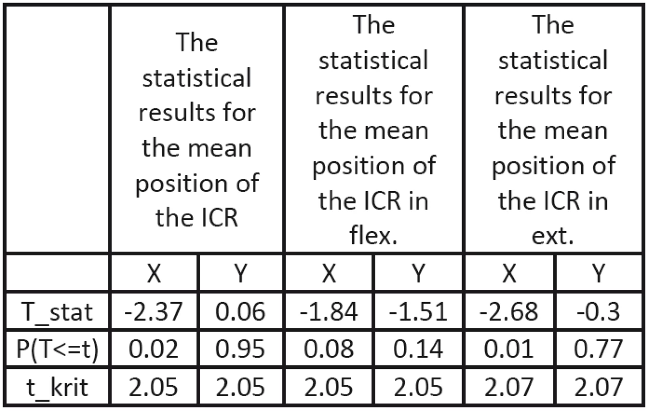
4. The results of the statistical analysis for the FSU of L<sub>4</sub>/<sub>5</sub> neighbouring the implanted artificial disc. 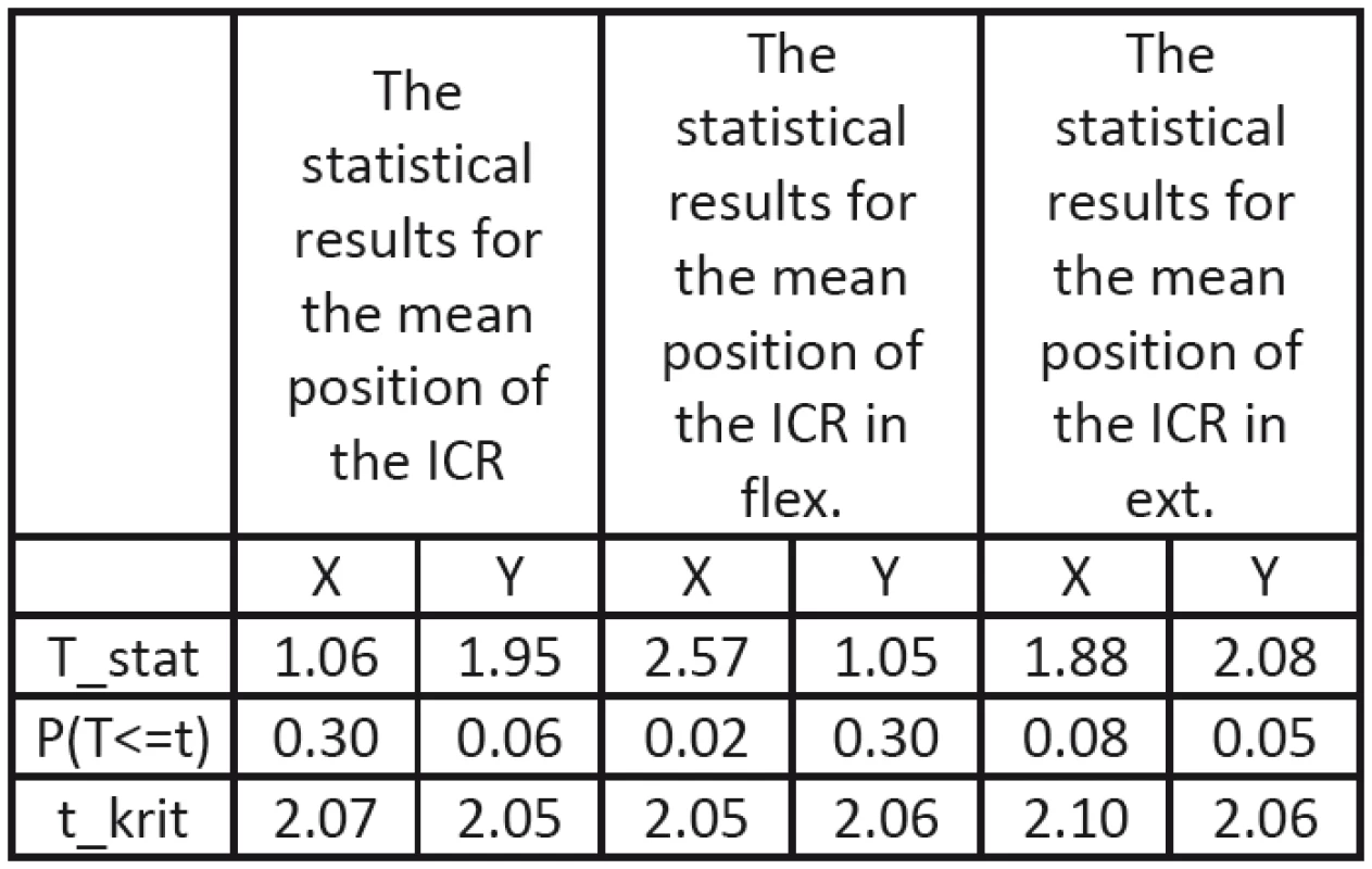
The results of the statistical analysis proved that the artificial disc influenced the kinematics not only in the area of L5/6, where the disc was implanted, but also in the area of the neighbouring FSU, L4/5. From the statistical point of view, this influence was significant especially for the horizontal change in the position of the ICR during the flexion/extension movement in sagittal plane. As regards the vertical change, this influence was obvious especially in case of the FSU neighbouring the area of implantation.
Discussion
The first part of the experiment was focused on kinematical analysis of two neighbouring FSUs, L4/5 and L5/6. The aim was to assess the mean position of the ICR during the whole loading cycle of flexion/
extension movement and its position in maximal flexion and extension. Considering anatomical dimensions of porcine lumbar spine, the results confirmed our hypothesis that the ICR was situated close to the spinal canal. The reason for this arises from properties of the ICR as it represents an area of zero-net-force point of application and thus minimal deformation [6, 10]. This is very useful, because the spinal canal contains important structures, the spinal cord and nerves, which are very prone to any kind of deformation. Although this hypothesis corresponds to some other studies [10, 12, 13], there are some that don’t agree and position the ICR to a different places in FSUs [6]. It’s therefore possible to assume that the position of the ICR, as the whole kinematics of FSUs, can depend on a lot of factors associated with the setup of the measurement.The results also showed and confirmed our assumption that the ICR seemed to be an adequate and objective parameter for the kinematics assessment. Small deviations could be caused especially by unique-ness of each spine, differences in condition of each sample, age, or imperfect rigidity of the loading mechanism. Despite all these slight deviations however, the results proved that the position of the ICR was comparable across all samples.
The last part dealt with the comparative kinematical analysis after the implantation of the artificial disc in the area of L5/6. The results confirmed our hypothesis that the contemporary artificial disc, developed by ProSpon, spol. s r.o., changed kinematics not only in the area of L5/6, but also in the neighbouring FSU, L4/5. This fact could be one of reasons, why these artificial discs, of a ball-and-socket type, mostly fail, as they change the position and conditions of loading in each structure of a FSU. The kinematics might have been changed due to different rigidity before and after implantation of the artificial disc, due to imbalance of forces after the implantation or due to the artificial disc itself.
The statistical analysis showed that the change of kinematics was significant especially for the horizontal change in the position of the ICR in L5/6 during the flexion/extension movement in sagittal plane. As regards the neighbouring FSU (L4/5), the change of kinematics was also significant along the vertical axis in sagittal plane. The reason for that could be the design of the artificial disc, its material, or the technique of implantation. Unfortunately these possible influences were not studied in this work and should be a part of an ongoing, more-detailed research.
Conclusion
The work dealt with the kinematical analysis of the cadaveric porcine lumbar spine samples loaded by flexion/extension movement. For this purpose, the unique loading mechanism and its control were designed and constructed to imitate the real loading of a spine. This device can also provide other kinematical analyses, studying different movements or their combinations.
The results of kinematical analysis of two neighbouring FSUs, L4/5 and L5/6, and also the comparative analysis after the implantation of the artificial disc into the area of L5/6 confirmed our hypotheses. The ICR seems to be an adequate, objective parameter for assessing the kinematical analysis; its position is similar across all samples and located very close to the spinal canal. The contemporary artificial disc, developed by ProSpon, Ltd., doesn’t satisfy the needs, as it changes the kinematics not only in the area of implantation, but also in the neighbouring FSU. This might be one of the reasons of their early failure.
Following research should be focused not only on more-detailed description of the kinematics, but also on materials, design and a technique of implantation of artificial discs.
Acknowledgement
The work was funded by the Technology Agency of the Czech Republic TA01010860. This work was supported by Czech Technical University’s foundation SVK 46/15/F7.
Ing. Luboš Tomšovský
Department of Natural Sciences
Faculty of Biomedical Engineering
Czech Technical University in Prague
nám. Sítná 3105, CZ-272 01 Kladno
E-mail: lubostomsovsky@gmail.com
Phone: +420 603 309 876
Sources
[1] Herkowitz, H., N., Dvorak, J., Bell, G., R., Nordin, M., Grob, D.: The Lumbar Spine. The: Official Publication of the International Society for the Study of the Lumbar Spine, 3rd Edition. Philadelphia Lippincott Williams & Wilkins, 2004, p. 976. ISBN 0781742978.
[2] Palecek, T., Lipina R.: Bolesti bederni patere degenerativniho puvodu – Low Back Pain syndrom. Interni medicina pro praxi, 2004, vol. 3, p. 115–118. ISSN 1214-8687.
[3] Shiri, R., Karppinen, J., Leino-Arjas, P., Solovieva, S., Viikari-Juntura, E.: The Association Between Obesity and Low Back Pain: A Meta-Analysis. American Journal of Epidemiology, 2009, vol. 171, no. 2, p. 135–154. DOI: 10.1093/aje/kwp356. ISSN 0002-9262.
[4] Borenstein, D., G.: Chronic Low Back Pain. Rheumatic Disease Clinics of North America, 1996, vol. 22, no. 3, p. 439–456. DOI: 10.1016/S0889-857X(05)70281-7. ISSN 0889857x.
[5] Meucci, R., D., Fassa, A., G., Faria, N., M., X.: Prevalence of chronic low back pain: systematic review. Revista de Saúde Pública, 2015, vol. 49, p. 1–10. DOI: 10.1590/S0034-8910.
2015049005874. ISSN 1518-8787.
[6] Bogduk, N.: Clinical anatomy of the lumbar spine and sacrum, 4th Edition. Elsevier/Churchill Livingstone, 2005, p. 250. ISBN 0443101191.
[7] Schwarzer, A., C., Aprill, CH., N., Derby, R., Fortin, J., Kine, G., Bogduk, N.: The prevalence and clinical features of internal disc disruption in patients with chronic low back pain. Spine, 1995, vol. 20, no. 17, p. 1878–1883.
[8] Punt, M., Visser, V.M., Van Rhijn, L.W., Kurtz, S.M., Antonis, J., Schurink, G.W.H., Van Ooij, A.: Complications and reoperations of the SB Charité lumbar disc prosthesis: experience in 75 patients. European Spine Journal, 2007, vol. 17, no. 1,
p. 36–43. DOI: 10.1007/s00586-007-0506-8.
[9] Van Ooij, A., Oner, F.C., Verbout, A.J.: Complications of artificial disc replacement: a report of 27 patients with SB Charité disc. Journal of spinal disorders & techniques, 2003, vol. 16, no. 4, p. 369-383.
[10] Otahal, M.: Pocitacova a experimentalni analyza kinematiky patere. Praha, 2012. Disertacni prace. Ceske vysoke uceni Technicke v Praze. Fakulta strojni.
[11] Adams, M.A., Burton, K., Dolan, P., Bogduk, N.: The biomechanics of back pain, 2nd Edition. 2006, Elsevier/Churchill Livingstone. ISBN 0443100683.
[12] Wachovski, M.M., Mansour, M., Lee, C., Ackenhausen, A., Spiering, S., Fanghänel, J., Dumont, C., Kubein-Meesenburg, D., Nägerl, H.: How do spinal segments move?. Journal of biomechanics, 2009, vol. 42, no. 14, p. 2286–2293. DOI: 10.1016/j.jbiomech.2009.06.055.
[13] Park, K.: Assessment of movement distribution in the lumbar spine using the instantaneous axis of rotation. Journal of mechanical science and technology, 2014, vol. 28, no. 12, p. 5063–5067. DOI: 10.1007/s12206-014-1127-x.
[14] Keefe, D.F., O’Brien, T.M., Baier, D.B., Gatesy, S.M., Brainerd, E.L., Laidlaw, D.H.: Exploratory visualization of animal kinematics using instantaneous helical axes. Computer graphics forum, 2008, vol. 27, no. 3, p. 863–870. DOI: 10.1111/j.1467-8659.2008.01218.x.
[15] Hirt, M., Beran, M., Datko, M., Hejna, P., Chrastina, J., Janik, M., Komarekova, I., Krajsa, J., Novak, Z., Riha, I., Straka, L., Safr, M., Toupalik, P., Vlckova, A., Vojtisek, T., Votava, M., Zeleny, M.: Tupa poraneni v soudnim lekarstvi. 1.vyd. Grada Publishing, 2011, p. 192. ISBN 978-80-247-4194-9.
[16] Varlotta, G.P., Lefkowitz, T.R., Schweitzer, M., Errico, T.J., Spivak, J., Bendo, J.A., Rybak, L.: The lumbar facet joint: a review of current knowledge: part 1: anatomy, biomechanics, and grading. Skeletal Radiology, 2011, vol. 40, no. 1, p. 13–23. DOI: 10.1007/s00256-010-0983-4.
[17] Pearcy, M.J., Portek, I., Shepherd, J.: Three-dimensional x-ray analysis of normal movement in the lumbar spine. Spine, 1984, vol. 9, no. 3, p. 294–297. DOI: 10.1097/00007632-198404000-00013.
[18] Twomey, L.T., Taylor, R.J.: Sagittal movements of the human lumbar vertebral column: a quantitative study of the role of the posterior vertebral elements. Archives of physical medicine and rehabilitation, 1983, vol. 64, no. 7, p. 322–325.
[19] Li, G., Wang, S., Passias, P., Xia, Q., Li, G., Wood, K.: Segmental in vivo vertebral motion during functional human lumbar spine activities. European spine journal, 2009, vol. 18, no. 7, p. 1013–1021. DOI: 10.1007/s00586-009-0936-6.
[20] Kapandji, I.A.: The physiology of the joints: the trunk and the vertebral column, volume 3, 2nd edition (Trunk & Vertebral column). Churchill Livingstone, 1974, p. 256. ISBN 0443012091.
[21] Busscher, I., Ploegmakers, J.J.W., Verkerke, G.J., Veldhuizen, A.G.: Comparative anatomical dimensions of the complete human and porcine spine. European spine journal, 2010, vol. 19, no. 7, p. 1104–1114. DOI: 10.1007/s00586-010-1326-9.
[22] Aziz, H.N., Galbusera, F., Bellini, C.M., Mineo, G.V., Addis, A., Pietrabissa, R., Brayda-Bruno, M.: Porcine models in spinal research: calibration and comparative finite element analysis of various configurations during flexion-extension. Comparative medicine, 2008, vol. 58, no. 2, p. 174–179.
[23] Robertson, G., Caldwell, G., Hamill, J., Kamen, G., Whittlesey, S.: Research methods in biomechanics, 2nd edition. Human Kinetics, 2013, p. 440. ISBN 0736093400.
[24] Tomsovsky, L.: Experimentalni analyza kinematiky meziobratloveho skloubeni lumbalni patere. Kladno, 2015. Diplomova prace. Ceske Vysoke Uceni Technicke v Praze. Fakulta biomedicinskeho inzenyrstvi.
Labels
Biomedicine
Article was published inThe Clinician and Technology Journal

2017 Issue 2-
All articles in this issue
- PERISTALTIC FLOW OF LITHOGENIC BILE IN THE VATERI’S PAPILLA AS NON-NEWTONIAN FLUID IN THE FINITE-LENGTH TUBE: ANALYTICAL AND NUMERICAL RESULTS FOR REFLUX STUDY AND OPTIMIZATION
- /GD-TRACKER/ A SOFTWARE FOR BLOOD-BRAIN BARRIER PERMEABILITY ASSESSMENT
- EXPERIMENTAL ANALYSIS OF THE LUMBAR SPINE KINEMATICS
- RESPIRATORY SOUNDS AS A SOURCE OF INFORMATION IN ASTHMA DIAGNOSIS
- MEASUREMENT OF THE VALUES OF RADIOFREQUENCY ELECTROMAGNETIC FIELDS AROUND THE HEAD OF ADOLESCENTS
- The Clinician and Technology Journal
- Journal archive
- Current issue
- Online only
- About the journal
Most read in this issue- /GD-TRACKER/ A SOFTWARE FOR BLOOD-BRAIN BARRIER PERMEABILITY ASSESSMENT
- PERISTALTIC FLOW OF LITHOGENIC BILE IN THE VATERI’S PAPILLA AS NON-NEWTONIAN FLUID IN THE FINITE-LENGTH TUBE: ANALYTICAL AND NUMERICAL RESULTS FOR REFLUX STUDY AND OPTIMIZATION
- RESPIRATORY SOUNDS AS A SOURCE OF INFORMATION IN ASTHMA DIAGNOSIS
- MEASUREMENT OF THE VALUES OF RADIOFREQUENCY ELECTROMAGNETIC FIELDS AROUND THE HEAD OF ADOLESCENTS
Login#ADS_BOTTOM_SCRIPTS#Forgotten passwordEnter the email address that you registered with. We will send you instructions on how to set a new password.
- Career


